|
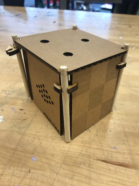
When beginning my synthesizer and enclosure project, I designed and printed my knobs first. I chose a diamond shape, and this process is explained in the 3D design section of my website. The 1M potentiometers has small diamonds and the 5k potentiometer has a larger diamond knob. Then I created the synthesizer with a breadboard and it took a lot of trouble shooting to make it work. I changed breadboards, the chip, the speaker and re-made the synthesizer multiple times, until it finally worked after many tries. Turns out there had been a short circuit and somewhere in the re-arranging it was fixed. The next step was to solder the synthesizer into a perfboard. Thankfully this process went well for me and the perfboard synthesizer worked the first time I soldered it! The visual design aspect was fun for me because I got to fiddle around with what to raster, score and cut. I love the idea of monotone, so I chose for my whole enclosure to be light blue, including my knobs. I created a checkered pattern to be rastered onto three of the tiles. My scoring aspect was my full name, with the same font as my sticker from the beginning of the year, and I placed it on the bottom corner of one tile. Finally my cut is holes placed into a diamond shape, for the sound of the speaker to pass through. I chose a blue, matte acrylic that happened to be shiny on the opposite side. This worked great with my idea to have checkers rastered onto the shiny side, so that those tiles would be both shiny and matte. And I decided to keep the other two tiles matte for some contrast. When it came to making my enclosure prototype, using the laser cutter went very smoothy. It turned out great except I forgot to place holes for the potentiometer and switch. I then went back into illustrator and placed the holes. I chose to put the potentiometers on the top tile in a triangle formation. In the prototype, the switch was fine, however my potentiometer holes were too small because I did not realize the screw part of it had to pass through too. Also, the holes were a little to close to the edges of the enclosure, not allowing enough space for the bottom of the potentiometers to be level with the tile. Once I figured out the right adjustment for the potentiometer holes, I placed the cardboard pieces together and completed my prototype. Finally, it was time to raster, score and cut the real acrylic. I was very meticulous about the tile sides because I didn't want there to be any mistakes. I had become a lot more comfortable with the laser cutter and the tiles turned out great! Next, with all my parts together I set up my final synthesizer! I am very pleased with the final product. Design Faults: I noticed after finishing my project that I had placed my name right where part of the tile slides into the wood. If I was able to retouch it, I would move my name to the bottom-center of the tile so that it wouldn't be blocked by the wood. In addition, weirdly, one of my faults worked out because I had soldered the switch to the synthesizer before fitting it through the hole. But because the hole was a little big I was able to push it through. The switch works perfectly and when you push it it won't go through, however it is a little loose. Looking forward to my 2D project I want to be more meticulous with my measurements. Also, when designing I want to think more about the overall look so certain elements don't get blocked (i.e. my name).
0 Comments
In my process of creating a successful synthesizer simulation, it was fairly easy due to our previous experience with building a synthesizer. I used the document Atari Punk Synthesizer document as my guide and easily found the components in Tinkercad and created the circuit. I then had to troubleshoot because the piezo wasn't making sound. So, I turned the potentiometers to see if that was the problem. It was, but in addition I hadn't realized that I needed to put in the range for each potentiometer and capacitor, i.e. 5k, .1uf. After filling in the range for each and turning the potentiometers the right direction my simulation worked perfectly.  Tinkercad Synthesizer
TED Talk Notes
1) https://www.hackster.io/pix3lot/pac-man-led-pixel-panel-costume-515666 - a family made like up pac man costumes by using arduino - the costumes were made with a laser cutter and then LED lights were covered on the outlines of the pac man characters and programmed in arduino to change faces 2) https://www.hackster.io/Frogger1108/homemade-arduino-pinball-machine-4a3314 - this person created a homemade pinball machine - they bought a pinball skeleton and then created the machine themselves using Arduino 3) https://www.hackster.io/iotboys/control-led-using-your-voice-command-b396df - here a person created voice controlling LED lights - they used Arduino in the building of the breadboard and with bluetooth allowed a voice to activate the lights turning on and off Creating this synthesizer was perfect for gaining more knowledge on different components. We used resistors and capacitors of different ranges. For example one potentiometer was 1M while another was 5k. In addition we used a 556 chip, speaker, and battery. I used the document given with the synthesizer directions to create my circuit. The guide helped my process run smoothly and the soldering was easy because we had learned how to use the solder beforehand. In the pictures you can see different stages of the creation of my circuit. Currently, I am troubleshooting my synthesizer because it is not emitting a sound. I just soldered one wire of my speaker so it can go into the positive rail more easily because beforehand the wire was very weak.
 To begin this synthesizer we grabbed all of our needed materials shown in the picture. Next I took out all the materials and laid them onto a piece of white paper where I labeled each part. From my teardown and after learning about classmates' teardowns I understood each part. As seen in the picture: There are four resistors, two 1M, and the others 5k and1k. In general, resistors control the amount of energy that can flow. Three capacitors of 0.01uF, 0.1uF and 10uF. Overall, capacitors are used to store charge and smooth out circuits. The other parts are a wire, a speaker, a switch (to turn the synthesizer on and off) and the breadboard (used to assemble the circuit). And the 556 chip has two timers in it that control oscillation and vibration.
Schematics
Soldering
Multimeters
Breadboards and Perfboards
SOURCES
http://www.radioworldcc.co.za/6.Radio-World-General-Products.html https://electronics.stackexchange.com/questions/49415/why-is-the-negative-contact-in-a-battery-bay-always-the-side-with-some-sort-of-s https://www.amazon.com/Bluecell-Multi-color-Flashing-Electronics/dp/B006LUZLNY https://www.sparkfun.com/products/11450 https://os.mbed.com/users/4180_1/notebook/rgb-leds/ For my etching project I chose two vectors from the noun project, the scale one was created by Sherrinford and the wave was created by artworkbean. I was immediately drawn to the scale outline and wanted to keep an ocean theme so I found a wave. Both icons easily went into illustrator because they were already vectors.The scales for the copper I imagined to look similar to shiny fish scales. I turned the one wave into multiple by copying and pasting the waves into three rows and then I connected them by grouping the singular waves together. I decided to do more than one etch, the scales bolted to copper on top and the waves on the tin's inner bottom. When stickers were printed the vinyl cutter cut them twice implying that I probably had more than one vector for the icons even though it wasn't visible in the outline. Thankfully this did not hamper my plan because I was still able to take out the lining of the scales and waves without pieces of the vinyl sticker separating. Next the waves were pressed onto the contact paper and then modified to fit the tin. I used left over contact paper to cover the sides so those parts wouldn't be etched. Using a battery and connecting one wire to the tin and the other I used to etch with a wet sponge attached. Following I quickly dried off the tin, took off the sticker and smudged beeswax onto the etch then heated it and sealed the etch using a paper towel to prevent rust.The scales took a long time to transfer onto the contact paper because each piece was separate and as I peeled the sticker I had to pick each individual part and connect it to the contact paper. Next I placed the sticker evenly on the copper and connected one wire to the plate and etched with the other onto the copper. After removing the sticker I loved the way the outline of the scales turned out on the copper! Now, my next steps are to bolt the copper plate onto the top of the tin, using the drill press and rivet tool.
Electricity
NOTES
Video REACTION It was fascinating how in Shih Chieh Huang’s childhood, he grew up around hardware stores and loved the night market, especially the lights. He loved to take apart toys and make invent fun environments. It was so clever how he tricked a light sensor into thinking it was night time by focusing on his eye and when his pupil reached the sensor, the light would turn on. He also made a complex hat machine which captured multiple people’s eyes. He advanced on that one idea and made multiple interesting sculptures. Like one, which turned around based on the eyes movement in the tv. Because of his interest in biology he did a research fellowship where he observed bioluminescent organisms in the ocean. Their use of light inspired many of his sculptures, which mimicked movement like an organism with different patterns of light. I found his innovations exciting! |
AuthorArchives
March 2018
Categories |


 RSS Feed
